Bottle-less Coolers
Water Filter System
By filtering at the source you can guarantee you are getting quality water. Bottleless water coolers can be installed reverse osmosis system, under sink system, or inline filters.
Water Cooler Installation
Water Cooler Location
The bottles-less water cooler location is dependant on distance to a nearby electrical outlet and water source (cold water line the cooler will hook into) with a drain.
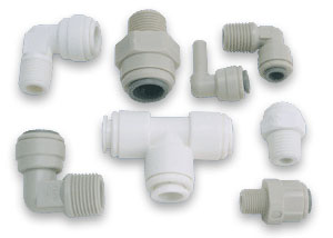
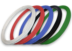
Filtration System & Tubing Connections
Follow the filter system’s installation instructions, but instead of connecting the output or ‘product’ water line to a faucet it you will be connecting it directly to the the bottle-less water cooler.
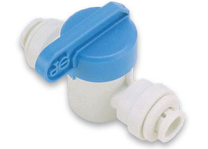
Check Tubing Connections
Turn on the shutoff valve or any type a ball shutoff valve the filter system may have and check the system and tubing connections for any leaks before you leave it in operation.
Countertop
![]() Countertop systems are a quick installation that takes only minutes and requires no tools. Simply remove the aerator (unscrewable metal ring on end of faucet spout) and determine whether it is a male or female threaded spout. If the spout is male, the diverter fitting can be screwed onto the spout. If the spout is female a threaded adaptor will have to be screwed on to the spout before the countertop diverter is attached.
Countertop systems are a quick installation that takes only minutes and requires no tools. Simply remove the aerator (unscrewable metal ring on end of faucet spout) and determine whether it is a male or female threaded spout. If the spout is male, the diverter fitting can be screwed onto the spout. If the spout is female a threaded adaptor will have to be screwed on to the spout before the countertop diverter is attached.
Reverse Osmosis
![]() Your RO system may be installed under a sink or in a basement. Do not install unit where it would be exposed to freezing temperatures. Connecting to an icemaker or other remote location can also be considered if a connection can be made without using more than 12″ of tubing, otherwise a delivery pump may be needed. Farther runs can be attempted and a pump can be added later only if needed.
Your RO system may be installed under a sink or in a basement. Do not install unit where it would be exposed to freezing temperatures. Connecting to an icemaker or other remote location can also be considered if a connection can be made without using more than 12″ of tubing, otherwise a delivery pump may be needed. Farther runs can be attempted and a pump can be added later only if needed.
Your Reverse Osmosis (RO) System has been tested to ensure it will operate correctly. The following periodic maintenance is recommended so your system will provide years of trouble-free service:
- Pre-filters (Sediment) – Once per year
- Pre-filter (Carbon Block(s)) – Once per year
- RO Membrane – Usually Every 2 years
- Post filter (Carbon) – Once per year
View our printable Reverse Osmosis Installation Guide to learn more.
Reverse Osmosis Installation Guide
Under Sink
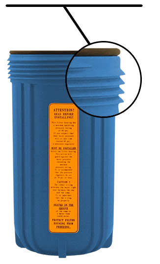
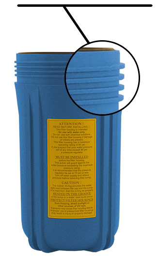
![]() Under sink installations can vary depending on whether you are installing it to a drinking water faucet or hooking it up to an ice maker in a refrigerator and what type of inlet pipe you are hooking it up to.
Under sink installations can vary depending on whether you are installing it to a drinking water faucet or hooking it up to an ice maker in a refrigerator and what type of inlet pipe you are hooking it up to.
Installing Under a Sink
Turn Off Water with Shut-Off Valve
Find the cold water supply to the sink/kitchen area and turn it off. It is typically located in the basement or crawlspace of a house. If there is no shutoff valve you may have to turn off the primary valve to all the water in your house.
Most of our under sink systems come with a faucet adaptor.
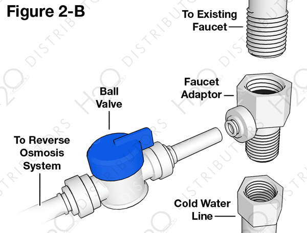
- After shutting off the valve, relieve the pressure by opening the handle on your faucet on the cold water side.
- Using an adjustable wrench or basin wrench, disconnect the riser tube from the bottom the faucet.
- Thread on the female side of the Faucet Adaptor to the male end of the faucet.
- Thread the riser tube on to the bottom of the Faucet Adaptor.
- Connect a length of 1/4″ of tubing between the fitting on the side of Faucet Adaptor and the Ball Valve.
Flexible Riser Tubes:
Most riser tubes that are used today are made of flexible material, either braided stainless steel, braided plastic or gray 3/8″ plastic tubing. These flexible tubes are the easiest to use with the Faucet Adaptor because the 2″ of additional space needed for the Faucet Adaptor can be easily accommodated by flexing this kind of riser. A shorter riser tube will not be needed.
Copper Riser Tubes:
If your riser tube is made of copper you will need to either make a bend in the copper to allow for the 2″ of space needed for the Faucet Adaptor. If the copper tube is 3/8″, bending it can be done easily by hand.
If the copper riser tube is larger than 3/8″ it is recommended that 2″ be cut from the bottom of the riser to allow for the space needed. A copper tubing cutter is the ideal tool for making this cut although a hack saw can be used. If a cut is made, a new compression ring (not supplied) will need to be installed to make a new water tight connection with the riser tube and the angle stop shut-off valve.
The self-piercing valve, which is supplied, is designed for use with 3/8" to 1/2" OD copper or chrome plated copper tubing, CPVC, & flexible gray riser tubes at least 3/8" in size. It should not be used on ribbed, corrugated, reinforced plastic or steel braided tubing. Ask your local dealer what alternatives can be used in place of the self-piercing valve if one cannot be used under your sink.
Installation using copper tubing/pipe or tubing, CPVC, and gray flexible riser tubes: (See Figure 2-A)
- Before installing saddle valve, make sure piercing lance does not protrude beyond rubber gasket.
- Assemble saddle valve on tube/pipe (As shown in Figure 3)
- Turn handle clockwise until it stops to pierce tube/pipe, (Valve is closed in this position)
- Turn on water supply to pressure cold water line.
- Snug nut/seal with wrench around valve stem.
- Connect tubing to feed water valve using brass compression nut, stiffener insert and plastic sleeve.
- To open valve, turn handle counterclockwise.
Saddle valve installations with other metal pipe:
- Drill 3/16″ hole at desired location.
- Make sure piercing lance does not protrude beyond rubber gasket.
- Assemble saddle valve on pipe, aligning with hole.
- Turn saddle valve handle clockwise to close valve.
- Tighten nut/seal around valve stem with wrench.
- Connect tubing to feed water valve using brass compression nut, stiffener insert and plastic sleeve.
- Turn on cold water supply.
- To open valve, turn handle counterclockwise.
Installing on an Ice Maker
Turn Off Water with Shut-Off Valve
Find the cold water supply to the sink/kitchen area and turn it off. It is typically located in the basement or crawlspace of a house. If there is no shutoff valve you may have to turn off the primary valve to all the water in your house.
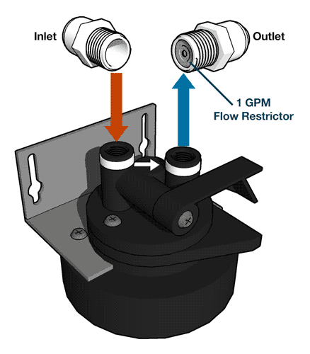
Connect Tubing
???
Installing Drinking Water Faucet
Our reverse osmosis installation guide has a set of common faucet installation instructions that can be used for our drinking water faucets.
UV Purifiers
![]() Installation of ultraviolet systems can vary from model to model. Please find your UV system, click on model number and check the right-hand column of the page. Below the product photo should be a link to a PDF service manual with instructions on installing the system.
Installation of ultraviolet systems can vary from model to model. Please find your UV system, click on model number and check the right-hand column of the page. Below the product photo should be a link to a PDF service manual with instructions on installing the system.
Water Softeners
Water softener systems have nearly identical installation instructions to whole house systems.
Well Water Systems
Well water systems have nearly identical installation instructions to whole house systems.
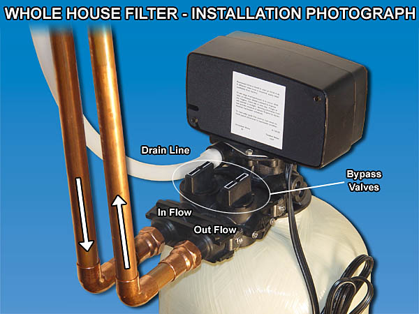
Whole House Systems
Diagram of Whole House Unit with Sediment Filter Diagram of Automatic Whole House Unit
![]() Whole house filters are typically recommended to be installed by an experienced professional installer. This could be a WQA-Certified Installer, a plumber, handyman, or you can do-it-yourself if you have the knowledge of working with pipe & fittings.
Whole house filters are typically recommended to be installed by an experienced professional installer. This could be a WQA-Certified Installer, a plumber, handyman, or you can do-it-yourself if you have the knowledge of working with pipe & fittings.
Because we recommend a professional installation these instructions will not detail how to solder copper pipe or how to join plastic piping systems. These skills are considered prerequisites to a successful installation.
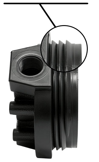
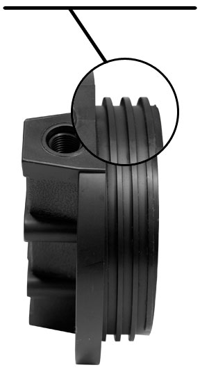
Our whole house systems use standard National Pipe Thread (NPT). The non-backwashing systems have female 3/4" NPT connections standard. The backwashing systems have male NPT fittings. 3/4" or 1" is available. Because of the use of standard pipe thread, the installation should be fairly straight forward to a person with plumbing experience.
How & Where to Install the System
In a nutshell, the unit should go as close to the main water line as possible, after the pressure reduction valve, but before any T or splits. A small section of the pipe is removed. Elbows, adaptors, & pipe or fitted so that an inlet line feeds the water into the system & an outlet line connects it back to your existing plumbing.
The main water line is usually located in a basement, crawl space, or garage. Sometimes it may be in a well house, laundry room, hot water closet, or possibly even under the stairs.
Non-Backwashing Systems
For your installation to be done the best way, replaceable cartridge housings should be firmly bracketed to a wall. These non backwashing systems should be installed with mechanical unions on each side of the tank to allow easy access for future maintenance. A pressure relief/flush port is another option to consider. This port makes flushing carbon dust and relieving pressure for filter changing much easier.
A permanent bypass assembly is recommended for a premium installation. This bypass gives the ability to completely bypass the filtration system and use untreated water at any time. It also allows for easy removal of the system in case you want to take it with you. To build a bypass it takes 3 shut-off valves (we recommend using ball valves), 2 T’s, some pipe and some additional labor.
We usually do not recommend this permanent bypass on a backwashing system because it has a built-in bypass.
Automatic Backwashing Systems
Installation of these systems requires the consideration of some drain water. When the system backwashes, it sends up to 5 gpm of water to the drain for about 10 minutes. This water can go into a laundry sink, floor drain, washing machine drain, or it can go outside on some bushes or grass. If none of these options are available, a P-trap and air gap drain assembly is recommended to make a connection to any existing drain pipe in the ceiling of a basement or garage. If no drain is available a non-backwashing system must be used.
Electricity is required to run the timer and the backwashing control valve. A standard wall outlet is sufficient. The unit only uses about $2 in electricity p/year. If your system has an ultra-violet light component, it also needs an outlet.
Flushing the System
In many filters, the first water that comes out should be run to drain. This first water carries a residue or dust, often has an off color, and needs to be flushed out before connecting the unit to service. A minimum of 25 gallons should be flushed through. The remainder can be flushed through out the garden hose or though the pipes in the home.
In a backwashing system, a backwash cycle can be initiated and this flushing process can be done automatically after the drain line has been connected. Simply plumb the unit in with the bypass valves closed and run the drain line. Turn on the water and check for leaks. Then initiate a backwashing cycle and then open the bypass valves. Allow the water will run to the drain for at least 10 minutes before putting the unit into service.
Installers
H2O is happy to provide assistance with installations by phone, free of charge. We have Certified Water Specialists on staff who have many years of field experience installing systems.
