Reverse Osmosis Installation Diagram

Also view our Exploded Diagrams at the bottom of this guide.
View our simplified Quick-Connect diagrams to see how…
- Pre-filters (Sediment) – Once per year
- Pre-filter (Carbon Block(s)) – Once per year
- RO Membrane – Usually Every 2 years
- Post filter (Carbon) – Once per year
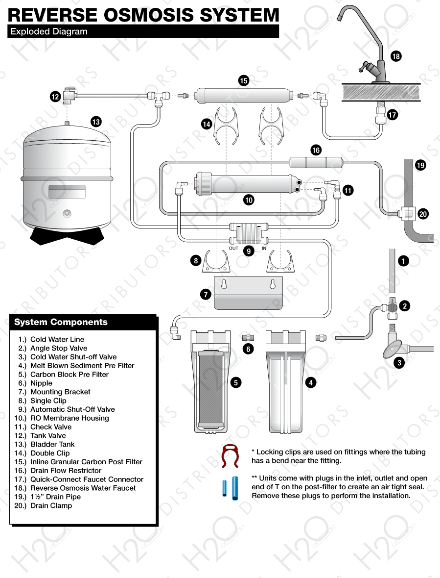
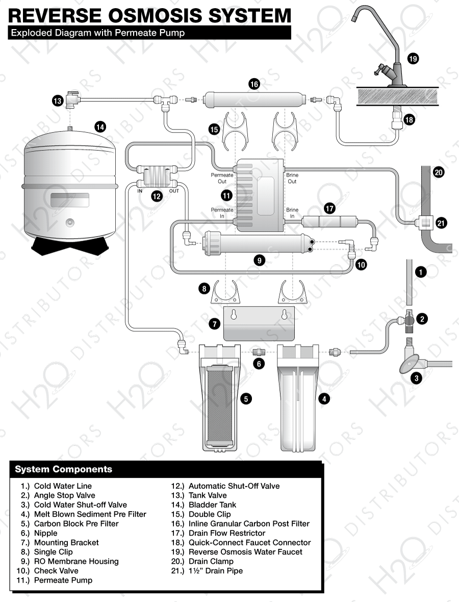
Reverse Osmosis System Components
RO Module
The RO module is the main component and holds the pre-filters, membrane, and post-filter. A bracket is provided so they can be mounted under the sink or in a basement.Angle Stop Valve
The angle stop valve connects to the cold water line to supply water to the RO system and provides an easy ability to shut off the water supply when servicing the unit.Pre-Filter #1
Melt Blown Polypropylene filter removes larger particles such as dirt, rust & sediment.Pre-Filter #2 (And 3 If Applicable)
10 Micron Carbon Block removes chlorine and chemical contaminants in the feed water and protects the RO membrane.Automatic Shut-Off Valve
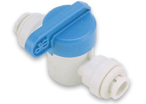
Automatic shut-off valve closes when the storage tank is full and shuts off the water supply to conserve water. The valve activates when the tank pressure is 2/3 of the feed pressure.Membrane
Reverse Osmosis Membrane Thin Film Composite Membranes reduces dissolved minerals, metals, and salts. In this process, harmful compounds are separated by the membrane from the water, and the contaminants are flushed to the drain.Post-Filter
A coconut shell activated carbon post filter is provided for a final “polish” and to remove tastes, odors and to provide great tasting water.Bladder Tank
Bladder tank holds RO purified water, ready to use.Drinking Water Faucet
The RO Faucet is used to dispense purified water when you want it.Drain Clamp
A wastewater saddle valve connects to the drain to remove reject water from the RO system.Tubing
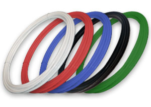
Tubing connects all RO components.Quick-Connect Fittings
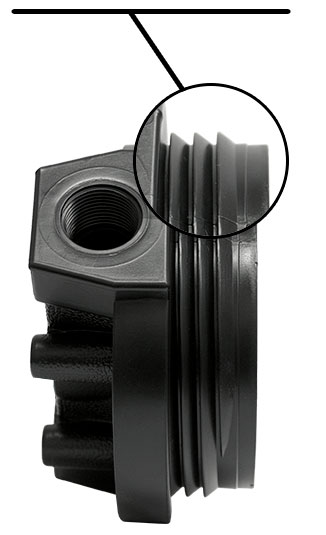
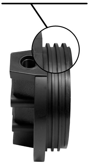
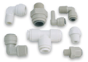
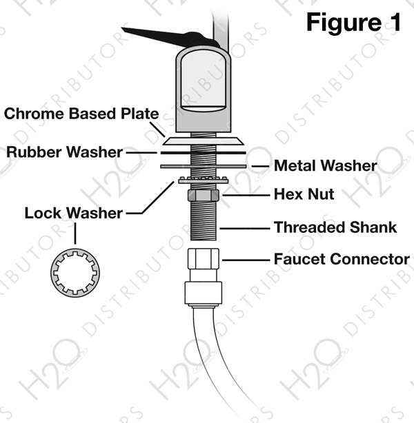
Quick-Connect fittings are used for necessary tubing connections. These fittings connect by pushing the tube into the fitting past a slight resistance until the tube bottoms out in the fitting. Simply make a clean cut in your tubing and gently push in the tubing until it will not go any further. To ensure that your tubing has made a snug fit, pull back gently on the tubing; it should catch. Always check for leaks to ensure a watertight connection. (see Figure 1).
Tools

- 3/8″ variable speed electric drill; (2,500 RPM is best for stainless steel)
- 1/8″, 1/4″ & 1/2″ metal cutting drill bits
- 1/8″, 1/4″ & 1/2″ concrete drill bits (for porcelain sinks)
- Phillips head screw driver
- 6″ adjustable wrench
- Teflon tape & Plastic tubing cutter
- Hammer & Center punch
System location
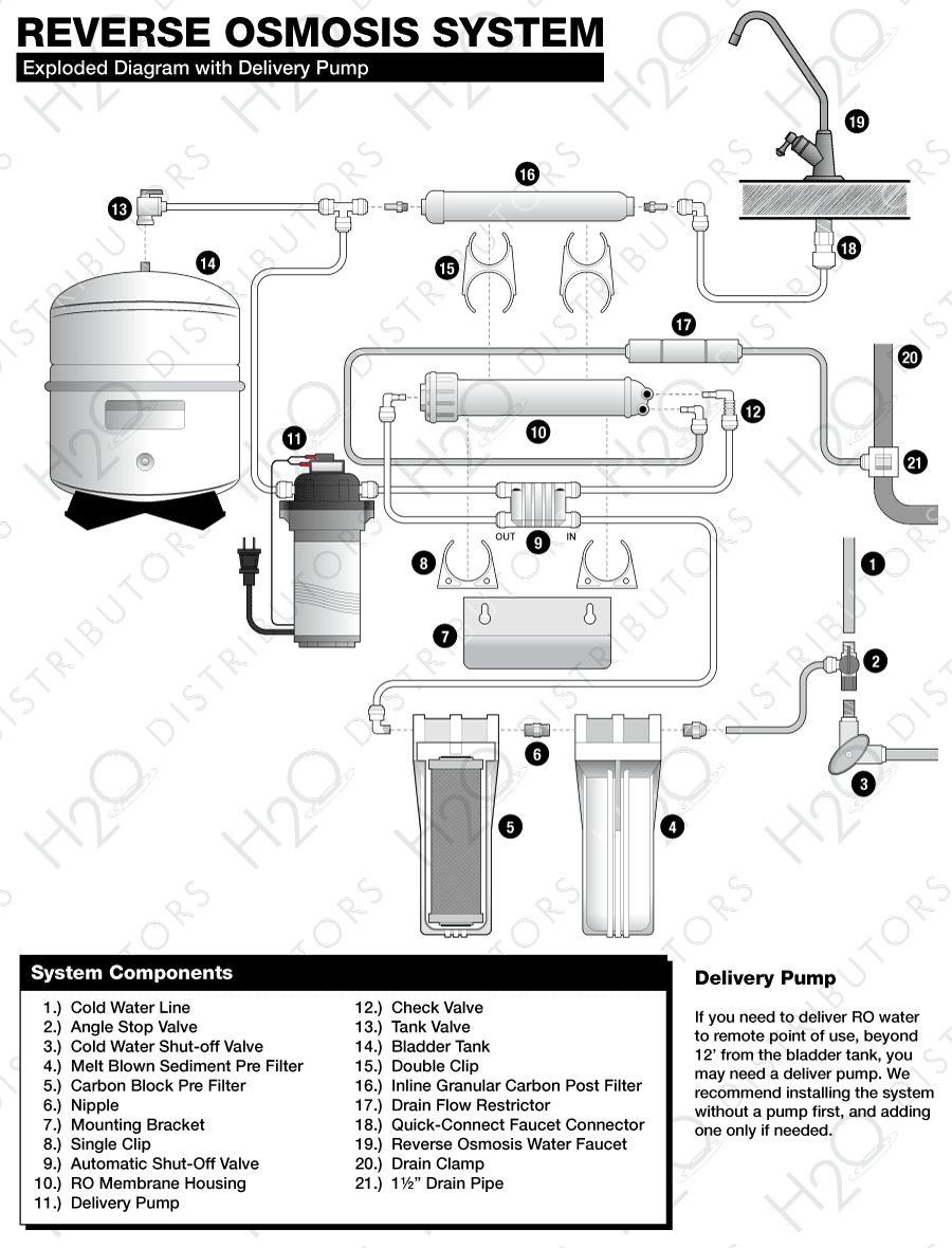
Your RO system may be installed under a sink or in a basement. Do not install unit where it would be exposed to freezing temperatures. Connecting to an icemaker or other remote location can also be considered if a connection can be made without using more than 12″ of tubing, otherwise a delivery pump may be needed. Farther runs can be attempted and a pump can be added later only if needed.
Faucet
should be placed on, or near the sink where drinking/cooking water is normally required. A 2″ flat surface is required to mount faucet if an existing hole is not available. The thickness of the mounting surface should not exceed 1-1/4″ or a faucet extension (not supplied) will be needed.Bladder Tank
maybe placed where it is convenient, within ten feet of the faucet. Under the sink or in a nearby cabinet or in basement rafters are excellent choices. Full tanks can weigh more than thirty pounds; so make sure any shelving used is secure. Bladder tank can be placed on its side or upright.RO Unit
may be mounted on either side of the sink, in the back of a cabinet, or in the basement. Mounting the unit on the left or the right side of the cabinet under the sink provides for easier access to the unit for future maintenance.Angle Stop Valve
is used to supply a feed water connection to the RO unit. Locate this assembly as close to the RO unit as possible. Connects between the top of your cold water shut-off valve and the bottom of the riser tube that runs between your cold water shut-off and the faucet. Ask your local dealer which alternatives can be used in place of the angle stop adaptor if one cannot be installed under your sink.A Drain Saddle
is used to make a waste water connection with your drain under the sink. This is designed to fit around a standard 1-1/2″ OD drainpipe. The drain saddle valve should always be installed before (above) the p-trap and on the vertical or horizontal tailpiece. Do not install the drain saddle near a garbage disposal to avoid clogging the drain line with debris.
System Preparation
Open shipping carton, remove components and check that all parts are present.
Installation Steps
All plumbing must be completed in accordance with state and local plumbing codes. Some municipalities may require installation by a licensed plumber. Check your local plumbing codes for more information.
-
1. Faucet Installation
If the sink has a sprayer, it may be disconnected for faucet installation. A pipe cap or plug will be necessary to seal the sprayer connection or sprayer can be left connected under the sink.
To make the faucet-mounting hole (if sprayer hole or other existing hole is not used), check below to make sure the drill will not interfere with anything below. A 2″ flat surface is required, not exceeding 1-1/4″ thickness.
The faucet should be positioned so it empties into the sink and the spout swivels freely for convenience. If the sink has a hole that can accommodate the RO faucet, no drilling is required. Proceed with mounting the faucet.
Installation procedures for Porcelain, Enamel, Ceramic on Metal, or Cast Iron:
Precautions must be taken to penetrate the porcelain through to the metal base and prevent chipping or scratching.
Procedures:
- Mark the center with center punch for the 1/4″ pilot hole.
- Carefully drill pilot hole with masonry pit through porcelain and stop when metal shows. (Use light pressure and slow speed)
- Switch the bit to a standard metal cutting bit to continue to cut through the metal below the porcelain surface.
- Continue to enlarge the pilot hole with larger masonry & metal cutting bits until the hole is 1/2″.
Installation procedures for stainless steel sinks
Procedures:
- Mark the center with center punch for the 1/4″ pilot hole.
- Drill the pilot hole.
- Continue to enlarge hole with larger size drill bit until it is 1/2″.
- Clean up sharp edges.
Note: Air Gap Faucets are required by some municipalities. These faucets require a 1-1/4″ hole in the sink rather than the 1/2″ hole required by the standard faucet included with the RO system. To make a 1 1/4″ hole to accommodate an air gap faucet requires special tools such as a chassis punch (stainless steel) or a Relton cutter (porcelain) if a large enough hole is not already available. Ask your local dealer for more information.
-
2. Mounting the Faucet

Disassemble hardware from the treaded shank. Chrome base plates and rubber washers slide up the shank to the faucet body.
Feed threaded shank through the sink hole and orient the faucet. From below sink, slide lock washer and hex nut over threaded shank and tighten with a wrench.
Note: It is best to have someone hold the faucet from above the sink to keep it from moving out of place. If this is not possible then tighten the hex nut until it is just slightly less than completely tight. Then turn the faucet base from above the sink, tightening it while orienting the faucet in the desired location.
-
3. Angle Stop Valve and Tubing Installation
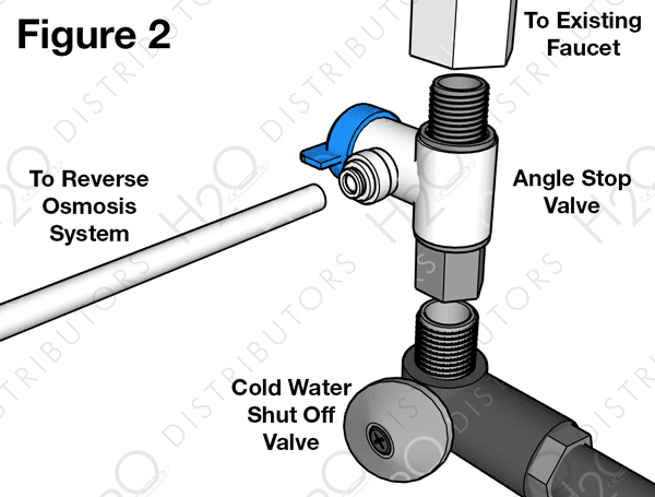
The John Guest Angle Stop Valve provides a simple, easy connection between the angle stop (cold water shut-off) and the bottom of the riser tube. The Angle Stop Valve has built-in shut-off and provides the feed supply connection for the reverse osmosis system.
Installation procedure: (See Figure 2)
- Shut-off the cold water supply using the angle stop shut-off located under your sink.
- After shutting off the valve, relieve the pressure by opening the handle on your faucet on the cold water side.
- Using an adjustable wrench, disconnect the riser tube from the existing cold water shut-off.
- Move the tubing away from the valve to make room for the John Guest Angle Stop Valve.
- Connect the swivel end of the John Guest Angle Stop Valve to the threads on the cold water shut-off. This connection should only be hand tight.
- Connect the riser tube to the male end of the John Guest Angle Stop Valve and tighten with a wrench.
- Connect a length of 1/4″ tubing between the John Guest Fitting on the Angle Stop Valve and the inlet of the RO unit.
Flexible Riser Tubes:
Most riser tubes that are used today are made of flexible material, either braided stainless steel, braided plastic or gray 3/8″ plastic tubing. These flexible tubes are the easiest to use with the John Guest Angle Stop Valve because the 2″ of additional space needed for the Faucet Adaptor can be easily accommodated by flexing this kind of riser. A shorter riser tube will not be needed.
Copper Riser Tubes:
If your riser tube is made of copper you will need to either make a bend in the copper to allow for the 2″ of space needed for the John Guest Angle Stop Valve. If the copper tube is 3/8″, bending it can be done easily by hand.
The John Guest Angle Stop Valve works with 3/8″ shut-off valves and riser tubes. In some cases, older plumbing may use a larger size shut-off and riser tube. In this case, it would be necessary to either replace the old valve and riser tube with new 3/8″ parts, or use an alternative connection to draw the water supply to the reverse osmosis system. Alternatives include self piercing valves, T fittings, and faucet adaptors that connect between the faucet and the top of the riser tube.
Please consult your distributor or an installation professional for additional assistance.
3-A. Self-Piercing Valve and Tubing Installation
The self-piercing valve (not supplied), is designed for use with 3/8″ to 1/2″ OD copper or chrome plated copper tubing, CPVC, & flexible gray riser tubes at least 3/8″ in size. It should not be used on ribbed, corrugated, reinforced plastic or steel braided tubing. Ask your local dealer what alternatives can be used in place of the self-piercing valve if one cannot be used under your sink.
Installation using copper tubing/pipe or tubing, CPVC, and gray flexible riser tubes: (See Figure 2-A)
- Turn off cold-water valve from under the sink or main water line valve for whole house.
- Before installing saddle valve, make sure piercing lance does not protrude beyond rubber gasket.
- Assemble saddle valve on tube/pipe (As shown in Figure 3)
- Turn handle clockwise until it stops to pierce tube/pipe, (Valve is closed in this position)
- Turn on water supply to pressure cold water line.
- Snug nut/seal with wrench around valve stem.
- Connect tubing to feed water valve using brass compression nut, stiffener insert and plastic sleeve.
- To open valve, turn handle counterclockwise.
Saddle valve installations with other metal pipe:
- Turn off cold water supply.
- Drill 3/16″ hole at desired location.
- Make sure piercing lance does not protrude beyond rubber gasket.
- Assemble saddle valve on pipe, aligning with hole.
- Turn saddle valve handle clockwise to close valve.
- Tighten nut/seal around valve stem with wrench.
- Connect tubing to feed water valve using brass compression nut, stiffener insert and plastic sleeve.
- Turn on cold water supply.
- To open valve, turn handle counterclockwise.
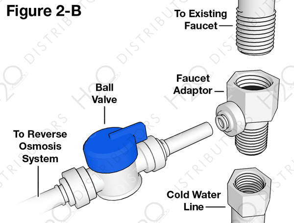
3-B. Faucet Adaptor, Ball Valve and Tubing Installation
The Faucet Adaptor (not supplied) and Ball Valve (not supplied) will work with all standard kitchen faucets and provide a reliable connection to supply feed water to the RO unit.
Installation procedure: (See Figure 2-B)
- Shut-off the cold water supply using the angle stop shut-off located under your sink.
- After shutting off the valve, relieve the pressure by opening the handle on your faucet on the cold water side.
- Using an adjustable wrench or basin wrench, disconnect the riser tube from the bottom the faucet.
- Thread on the female side of the Faucet Adaptor to the male end of the faucet.
- Thread the riser tube on to the bottom of the Faucet Adaptor.
- Connect a length of 1/4″ of tubing between the fitting on the side of Faucet Adaptor and the Ball Valve.
Flexible Riser Tubes:
Most riser tubes that are used today are made of flexible material, either braided stainless steel, braided plastic or gray 3/8″ plastic tubing. These flexible tubes are the easiest to use with the Faucet Adaptor because the 2″ of additional space needed for the Faucet Adaptor can be easily accommodated by flexing this kind of riser. A shorter riser tube will not be needed.
Copper Riser Tubes:
If your riser tube is made of copper you will need to either make a bend in the copper to allow for the 2″ of space needed for the Faucet Adaptor. If the copper tube is 3/8″, bending it can be done easily by hand.
If the copper riser tube is larger than 3/8″ it is recommended that 2″ be cut from the bottom of the riser to allow for the space needed. A copper tubing cutter is the ideal tool for making this cut although a hack saw can be used. If a cut is made, a new compression ring (not supplied) will need to be installed to make a new water tight connection with the riser tube and the angle stop shut-off valve.
-
4. Drain Saddle Valve Installation
A Drain Saddle is used to make a wastewater connection with the drain under the sink, which is designed to fit around a standard 1-1/2″ OD drainpipe. The drain saddle valve should always be installed before (above) the p-trap and on a vertical or horizontal drain. Do not install the drain saddle near a garbage disposal to avoid clogging the drain line with debris.
Installation procedure: (See Figure 3)
- Position the drain saddle valve at selected location and mark for the opening.
- Drill 1/4″ hole at mark through one side of pipe.
- Remove backing from gasket and place adhesive side to the fitting half of drain clamp around hole.
- Position both halves of drain saddle on drain pipe so the opening aligns with drilled hole. Use a small drill bit to verify that drain clamp is properly aligned.
- Secure drain saddle clamp on valve with bolts and nuts provided. (Do not over tighten and make sure there is equal space between saddle halves on each side)
-
5. Initial Tubing Connections
For convenience on under sink installations it may be advisable to complete under sink tubing connections at this time.
-
6. RO Component Installation
Cartridge Installation Required
The sediment cartridge, carbon block cartridge(s), and reverse osmosis membrane must all be installed in the RO unit. The cartridges are provided in sanitary packaging. Please wash hands or use gloves when handling the cartridges.
The melt blown polypropylene sediment cartridge is the first on the inlet side, followed by the carbon block cartridge(s) (CBC10-10). Both of these cartridges can be installed with either end in first. The membrane goes into the membrane housing with the o-ring end first. Be sure RO Membrane is pushed into Membrane housing as far as it will go.
-
7. RO Unit Installation
The RO unit is normally mounted to the right or left sink cabinet sidewall, depending on where supply tank is to be located. Generally the unit is installed at the front of the cabinet and the tank at the rear.
To mount the unit, elevate it at least 2″ off the floor, level it and mark the location of mounting holes needed. Drill hole for mounting screws and install screws allowing the mounting bracket slots to slip over them.
Note: If the cabinet sidewalls are not solid, unit may sit on the floor with screws used just to keep it against the cabinet in a vertical position.
-
8. Pre-Fill and Supply Tank Placement
Pre-filling the storage tank is recommended so there is sufficient pressure to check for leaks and water to flush the carbon post filter. To do this connect the feed line that will serve the RO unit directly to the bladder tank. A 3/8″ x 1/4″ reducer is provided for this purpose. Allow the water to fill the bladder until it stops. Close to tank valve, shut off the feed pressure, release the tube from the reducer and remove the reducer from the tank valve.
The supply tank should be placed under the counter or within 10 feet of the RO unit.
Note: Tanks are pre-pressurized with air at 7 psi.
-
9. Final Tubing Connections
With all components in place, complete final tubing connections with these guidelines:
- Tubing should follow contour of the cabinets.
- Cut tubing to correct length using square cuts and a proper cutting tool.
- Make sure there are no crimps in the tubing.
- Keep tubing from the RO unit to the tank and faucet as short as possible for good flow.
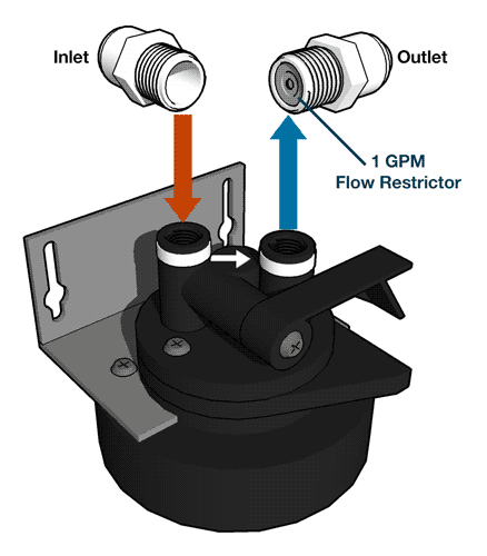
- The Drain line is a short 1/4″ tube connected to the membrane housing. On this tube is a 3″ cylindrical drain flow restrictor. This is where the drain line connects to the RO unit. Do not remove the drain flow restrictor as this will cause a failure in the system.
Icemaker hookup
(optional and requires a T fitting and additional shut-off valve not supplied with RO unit)
The RO unit can be connected to any standard refrigerator icemaker or ice maker/water dispenser.
To complete this operation, connect a T with a shut off valve into the faucet tubing and route tubing to the refrigerator. (Hooking up to existing copper tubing is not recommended due to possible corrosion) Turn off icemaker inside freezer prior to turning off the existing tap water supply line to the refrigerator. Turn on the icemaker after the RO system has been drained several times and the tank has a full supply of water.
Icemaker lines are often run in the rafters of unfinished basements or finished basements with drop ceilings and then up to the fridge. If the basement has a hard ceiling, this won’t be an option and the line would have to be run through cabinets. In cases where a basement or cabinets connecting sink and fridge are not available, icemaker connections cannot be made.
Note: Before any service is performed on the RO system, turn off icemaker valve and icemaker unit. Turn back on only after RO system has been sanitized and flushed out.
System Start-Up
Prior to start-up
- Check all fitting connections.
- Open ball valve, allow system to pressurize and check for leaks.
- Open valve on bladder tank and open faucet until water flows.
- Close faucet, wait five minutes and check for leaks.
- Allow system to produce a full tank of RO water. (2-3 hours)
Flushing System and Checking Operation
- Flip the faucet lever up and this will keep faucet on. Do this and allow tank to completely drain of all water.
Do not use this water! - Close faucet and re-inspect system for leaks.
- Allow system to produce water for 4 hours, at this point the bladder tank will be full.
- Open faucet again and allow tank to empty for a second time.
Do not use this water! - Close faucet and allow unit to produce another tank of water.
- At this point supply line to ice maker connection (optional) may be opened and RO water is ready to be consumed.
Replacing Filters & Sanitizing the System
Each year the filters in the system should be replaced. Usually the membrane can be replaced every other year, but the pre-filters and post-filter should be changed annually and in some cases more often.
Filter Replacement
- Turn off valve on RO bladder tank.
- Turn off feed water pressure.
- Open RO faucet to relief pressure.
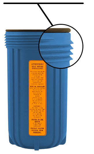
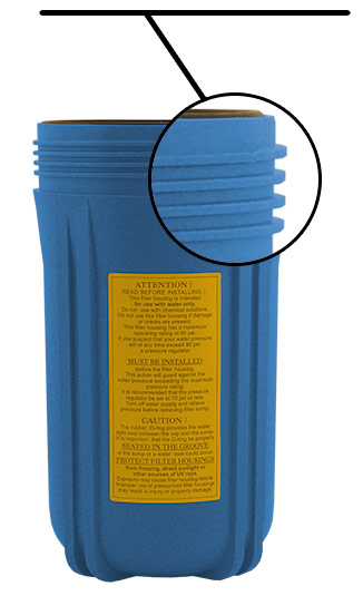
- Using the supplied housing wrench remove the filter housing.
- Discard old filters.
- Clean filter housings with a cleaning brush.
- Follow sanitizing steps in “Sanitizing the System” section
- Install new filters in system.
- Remove and replace GAC Post filter. Remove fittings from old post filter, re-apply Teflon tape and install fittings in new post filter.
- Turn on feed pressure.
- Open tank valve.
- Allow water in tank to flush out post filter and run to drain until empty. Run 2 more complete batches to drain before using water.
Membrane Replacement
- Remove the supply tube from the end of the membrane housing that has only 1 tube.
- Unthread the cap from the membrane housing.
- Remove membrane using a pair of pliers.
- Clean membrane housing with a brush.
Note: When installing a new membrane be sure to push the membrane into the housing as far as it will go. Each time the filters are replaced it is recommended that the system be sanitized.
Sanitizing the System
After all filters are removed from the system, housings have been cleaned, tank is empty, and faucet is open…
- Add 1 gallon of water to a clean bucket.
- Add 1 teaspoon of unscented household bleach.
- Add 1 cup of this solution to each filter housing.
- Tighten filter housings with solution on RO assembly.
- Connect membrane housing and feed tube.
- Open tank valve and feed pressure valve.
- Allow water to fill the RO housing assembly until water comes out of faucet.
- Close the faucet.
- Allow water to run for 5 minutes.
- Shut-off feed pressure.
- Allow solution to stand for 30 minutes.
- Open faucet and allow system to drain.
- Remove water from housings before installing new filters and membrane.
- Install new filters, tighten housings, and reconnect all tubing connections.
- Open feed pressure valve and check for leaks.
- Allow the system to make a full tank of water.
- Run 2 cycles to drain to rinse out sanitizing solution before using water.
Troubleshooting
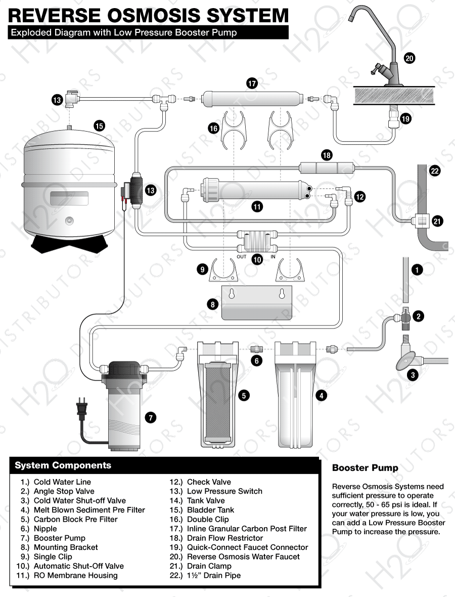
RO Systems are highly sensitive to pressure and temperature. RO Membranes always perform better under higher pressures. They produce more water, faster, and of better quality with high pressure. The vast majority of problems with RO Systems are a result of low pressure. The effects of low pressure include water constantly running to the drain, slow water production and low water volume available in storage tank. In these cases where low pressure exists, a booster pump will be required.
On the following page is a table showing RO Membrane performance over a range of temperatures and pressures. Membranes are tested at 65 psi of pressure and temperature of 77 degrees. For each incremental change in either variable, membrane performance changes accordingly. Higher pressures increase production and vice versa.
To troubleshoot a poor performing RO System an accurate measure of the pressure and temperature of water will be required. This will require a pressure gauge to determine exactly what the water pressure is that is feeding the membrane. Descriptions of water pressure such as good, high or strong, unfortunately, are no help in diagnosing an RO System.

View This Chart SeparatelyPressure Temperature Chart | ||||||||||||||||
| Temp °F | 35 PSI | 40 PSI | 45 PSI | 50 PSI | 55 PSI | 60 PSI | 65 PSI | 70 PSI | 75 PSI | 80 PSI | 85 PSI | 90 PSI | 95 PSI | 100 PSI | 105 PSI | 110 PSI |
| 45° | 0.2321 | 0.2653 | 0.2985 | 0.3316 | 0.3648 | 0.3979 | 0.4311 | 0.4643 | 0.4974 | 0.5306 | 0.5638 | 0.5969 | 0.6301 | 0.6632 | 0.6964 | 0.7296 |
| 46° | 0.2417 | 0.2762 | 0.3108 | 0.3453 | 0.3798 | 0.4144 | 0.4489 | 0.4834 | 0.5179 | 0.5525 | 0.5870 | 0.6215 | 0.6561 | 0.6906 | 0.7251 | 0.7597 |
| 47° | 0.2513 | 0.2872 | 0.3231 | 0.3590 | 0.3949 | 0.4308 | 0.4667 | 0.5026 | 0.5385 | 0.5744 | 0.6103 | 0.6462 | 0.6821 | 0.7179 | 0.7538 | 0.7897 |
| 48° | 0.2609 | 0.2981 | 0.3354 | 0.3726 | 0.4099 | 0.4472 | 0.4844 | 0.5217 | 0.5590 | 0.5962 | 0.6335 | 0.6708 | 0.7080 | 0.7453 | 0.7826 | 0.8198 |
| 49° | 0.2704 | 0.3091 | 0.3477 | 0.3863 | 0.4250 | 0.4636 | 0.5022 | 0.5409 | 0.5795 | 0.6181 | 0.6568 | 0.6954 | 0.7340 | 0.7726 | 0.8113 | 0.8499 |
| 50° | 0.2800 | 0.3200 | 0.3600 | 0.4000 | 0.4400 | 0.4800 | 0.5200 | 0.5600 | 0.6000 | 0.6400 | 0.6800 | 0.7200 | 0.7600 | 0.8000 | 0.8400 | 0.8800 |
| 51° | 0.2896 | 0.3309 | 0.3723 | 0.4137 | 0.4550 | 0.4964 | 0.5378 | 0.5791 | 0.6205 | 0.6619 | 0.7032 | 0.7446 | 0.7860 | 0.8274 | 0.8687 | 0.9101 |
| 52° | 0.2991 | 0.3419 | 0.3846 | 0.4274 | 0.4701 | 0.5128 | 0.5556 | 0.5983 | 0.6410 | 0.6838 | 0.7265 | 0.7692 | 0.8120 | 0.8547 | 0.8974 | 0.9402 |
| 53° | 0.3087 | 0.3528 | 0.3969 | 0.4410 | 0.4851 | 0.5292 | 0.5733 | 0.6174 | 0.6615 | 0.7056 | 0.7497 | 0.7938 | 0.8379 | 0.8821 | 0.9262 | 0.9703 |
| 54° | 0.3183 | 0.3638 | 0.4092 | 0.4547 | 0.5002 | 0.5456 | 0.5911 | 0.6366 | 0.6821 | 0.7275 | 0.7730 | 0.8185 | 0.8639 | 0.9094 | 0.9549 | 1.0003 |
| 55° | 0.3279 | 0.3747 | 0.4215 | 0.4684 | 0.5152 | 0.5621 | 0.6089 | 0.6557 | 0.7026 | 0.7494 | 0.7962 | 0.8431 | 0.8899 | 0.9368 | 0.9836 | 1.0304 |
| 56° | 0.3374 | 0.3856 | 0.4338 | 0.4821 | 0.5303 | 0.5785 | 0.6267 | 0.6749 | 0.7231 | 0.7713 | 0.8195 | 0.8677 | 0.9159 | 0.9641 | 1.0123 | 1.0605 |
| 57° | 0.3470 | 0.3966 | 0.4462 | 0.4957 | 0.5453 | 0.5949 | 0.6444 | 0.6940 | 0.7436 | 0.7932 | 0.8427 | 0.8923 | 0.9419 | 0.9915 | 1.0410 | 1.0906 |
| 58° | 0.3566 | 0.4075 | 0.4585 | 0.5094 | 0.5603 | 0.6113 | 0.6622 | 0.7132 | 0.7641 | 0.8150 | 0.8660 | 0.9169 | 0.9679 | 1.0188 | 1.0697 | 1.1207 |
| 59° | 0.3662 | 0.4185 | 0.4708 | 0.5231 | 0.5754 | 0.6277 | 0.6800 | 0.7323 | 0.7846 | 0.8369 | 0.8892 | 0.9415 | 0.9938 | 1.0462 | 1.0985 | 1.1508 |
| 60° | 0.3757 | 0.4294 | 0.4831 | 0.5368 | 0.5904 | 0.6441 | 0.6978 | 0.7515 | 0.8051 | 0.8588 | 0.9125 | 0.9662 | 1.0198 | 1.0735 | 1.1272 | 1.1809 |
| 61° | 0.3853 | 0.4403 | 0.4954 | 0.5504 | 0.6055 | 0.6605 | 0.7156 | 0.7706 | 0.8256 | 0.8807 | 0.9357 | 0.9908 | 1.0458 | 1.1009 | 1.1559 | 1.2109 |
| 62° | 0.3949 | 0.4513 | 0.5077 | 0.5641 | 0.6205 | 0.6769 | 0.7333 | 0.7897 | 0.8462 | 0.9026 | 0.9590 | 1.0154 | 1.0718 | 1.1282 | 1.1846 | 1.2410 |
| 63° | 0.4044 | 0.4622 | 0.5200 | 0.5778 | 0.6356 | 0.6933 | 0.7511 | 0.8089 | 0.8667 | 0.9244 | 0.9822 | 1.0400 | 1.0978 | 1.1556 | 1.2133 | 1.2711 |
| 64° | 0.4140 | 0.4732 | 0.5323 | 0.5915 | 0.6506 | 0.7097 | 0.7689 | 0.8280 | 0.8872 | 0.9463 | 1.0055 | 1.0646 | 1.1238 | 1.1829 | 1.2421 | 1.3012 |
| 65° | 0.4236 | 0.4841 | 0.5446 | 0.6051 | 0.6656 | 0.7262 | 0.7867 | 0.8472 | 0.9077 | 0.9682 | 1.0287 | 1.0892 | 1.1497 | 1.2103 | 1.2708 | 1.3313 |
| 66° | 0.4332 | 0.4950 | 0.5569 | 0.6188 | 0.6807 | 0.7426 | 0.8044 | 0.8663 | 0.9282 | 0.9901 | 1.0520 | 1.1138 | 1.1757 | 1.2376 | 1.2995 | 1.3614 |
| 67° | 0.4427 | 0.5060 | 0.5692 | 0.6325 | 0.6957 | 0.7590 | 0.8222 | 0.8855 | 0.9487 | 1.0120 | 1.0752 | 1.1385 | 1.2017 | 1.2650 | 1.3282 | 1.3915 |
| 68° | 0.4523 | 0.5169 | 0.5815 | 0.6462 | 0.7108 | 0.7754 | 0.8400 | 0.9046 | 0.9692 | 1.0338 | 1.0985 | 1.1631 | 1.2277 | 1.2923 | 1.3569 | 1.4215 |
| 69° | 0.4619 | 0.5279 | 0.5938 | 0.6598 | 0.7258 | 0.7918 | 0.8578 | 0.9238 | 0.9897 | 1.0557 | 1.1217 | 1.1877 | 1.2537 | 1.3197 | 1.3856 | 1.4516 |
| 70° | 0.4715 | 0.5388 | 0.6062 | 0.6735 | 0.7409 | 0.8082 | 0.8756 | 0.9429 | 1.0103 | 1.0776 | 1.1450 | 1.2123 | 1.2797 | 1.3470 | 1.4144 | 1.4817 |
| 71° | 0.4810 | 0.5497 | 0.6185 | 0.6872 | 0.7559 | 0.8246 | 0.8933 | 0.9621 | 1.0308 | 1.0995 | 1.1682 | 1.2369 | 1.3056 | 1.3744 | 1.4431 | 1.5118 |
| 72° | 0.4906 | 0.5607 | 0.6308 | 0.7009 | 0.7709 | 0.8410 | 0.9111 | 0.9812 | 1.0513 | 1.1214 | 1.1915 | 1.2615 | 1.3316 | 1.4017 | 1.4718 | 1.5419 |
| 73° | 0.5002 | 0.5716 | 0.6431 | 0.7145 | 0.7860 | 0.8574 | 0.9289 | 1.0003 | 1.0718 | 1.1432 | 1.2147 | 1.2862 | 1.3576 | 1.4291 | 1.5005 | 1.5720 |
| 74° | 0.5097 | 0.5826 | 0.6554 | 0.7282 | 0.8010 | 0.8738 | 0.9467 | 1.0195 | 1.0923 | 1.1651 | 1.2379 | 1.3108 | 1.3836 | 1.4564 | 1.5292 | 1.6021 |
| 75° | 0.5193 | 0.5935 | 0.6677 | 0.7419 | 0.8161 | 0.8903 | 0.9644 | 1.0386 | 1.1128 | 1.1870 | 1.2612 | 1.3354 | 1.4096 | 1.4838 | 1.5579 | 1.6321 |
| 76° | 0.5289 | 0.6044 | 0.6800 | 0.7556 | 0.8311 | 0.9067 | 0.9822 | 1.0578 | 1.1333 | 1.2089 | 1.2844 | 1.3600 | 1.4356 | 1.5111 | 1.5867 | 1.6622 |
| 77° | 0.5385 | 0.6154 | 0.6923 | 0.7692 | 0.8462 | 0.9231 | 1.0000 | 1.0769 | 1.1538 | 1.2308 | 1.3077 | 1.3846 | 1.4615 | 1.5385 | 1.6154 | 1.6923 |
| 78° | 0.5480 | 0.6263 | 0.7046 | 0.7829 | 0.8612 | 0.9395 | 1.0178 | 1.0961 | 1.1744 | 1.2526 | 1.3309 | 1.4092 | 1.4875 | 1.5658 | 1.6441 | 1.7224 |
| 79° | 0.5576 | 0.6373 | 0.7169 | 0.7966 | 0.8762 | 0.9559 | 1.0356 | 1.1152 | 1.1949 | 1.2745 | 1.3542 | 1.4338 | 1.5135 | 1.5932 | 1.6728 | 1.7525 |
| 80° | 0.5672 | 0.6482 | 0.7292 | 0.8103 | 0.8913 | 0.9723 | 1.0533 | 1.1344 | 1.2154 | 1.2964 | 1.3774 | 1.4585 | 1.5395 | 1.6205 | 1.7015 | 1.7826 |
| 81° | 0.5768 | 0.6591 | 0.7415 | 0.8239 | 0.9063 | 0.9887 | 1.0711 | 1.1535 | 1.2359 | 1.3183 | 1.4007 | 1.4831 | 1.5655 | 1.6479 | 1.7303 | 1.8126 |
| 82° | 0.5863 | 0.6701 | 0.7538 | 0.8376 | 0.9214 | 1.0051 | 1.0889 | 1.1726 | 1.2564 | 1.3402 | 1.4239 | 1.5077 | 1.5915 | 1.6752 | 1.7590 | 1.8427 |
| 83° | 0.5959 | 0.6810 | 0.7662 | 0.8513 | 0.9364 | 1.0215 | 1.1067 | 1.1918 | 1.2769 | 1.3621 | 1.4472 | 1.5323 | 1.6174 | 1.7026 | 1.7877 | 1.8728 |
| 84° | 0.6055 | 0.6920 | 0.7785 | 0.8650 | 0.9515 | 1.0379 | 1.1244 | 1.2109 | 1.2974 | 1.3839 | 1.4704 | 1.5569 | 1.6434 | 1.7299 | 1.8164 | 1.9029 |
| 85° | 0.6150 | 0.7029 | 0.7908 | 0.8786 | 0.9665 | 1.0544 | 1.1422 | 1.2301 | 1.3179 | 1.4058 | 1.4937 | 1.5815 | 1.6694 | 1.7573 | 1.8451 | 1.9330 |
| 86° | 0.6246 | 0.7138 | 0.8031 | 0.8923 | 0.9815 | 1.0708 | 1.1600 | 1.2492 | 1.3385 | 1.4277 | 1.5169 | 1.6062 | 1.6954 | 1.7846 | 1.8738 | 1.9631 |
| 87° | 0.6342 | 0.7248 | 0.8154 | 0.9060 | 0.9966 | 1.0872 | 1.1778 | 1.2684 | 1.3590 | 1.4496 | 1.5402 | 1.6308 | 1.7214 | 1.8120 | 1.9026 | 1.9932 |
| 88° | 0.6438 | 0.7357 | 0.8277 | 0.9197 | 1.0116 | 1.1036 | 1.1956 | 1.2875 | 1.3795 | 1.4715 | 1.5634 | 1.6554 | 1.7474 | 1.8393 | 1.9313 | 2.0232 |
| 89° | 0.6533 | 0.7467 | 0.8400 | 0.9333 | 1.0267 | 1.1200 | 1.2133 | 1.3067 | 1.4000 | 1.4933 | 1.5867 | 1.6800 | 1.7733 | 1.8667 | 1.9600 | 2.0533 |
| 90° | 0.6629 | 0.7576 | 0.8523 | 0.9470 | 1.0417 | 1.1364 | 1.2311 | 1.3258 | 1.4205 | 1.5152 | 1.6099 | 1.7046 | 1.7993 | 1.8940 | 1.9887 | 2.0834 |
| 91° | 0.6725 | 0.7685 | 0.8646 | 0.9607 | 1.0568 | 1.1528 | 1.2489 | 1.3450 | 1.4410 | 1.5371 | 1.6332 | 1.7292 | 1.8253 | 1.9214 | 2.0174 | 2.1135 |
| 92° | 0.6821 | 0.7795 | 0.8769 | 0.9744 | 1.0718 | 1.1692 | 1.2667 | 1.3641 | 1.4615 | 1.5590 | 1.6564 | 1.7538 | 1.8513 | 1.9487 | 2.0462 | 2.1436 |
| 93° | 0.6916 | 0.7904 | 0.8892 | 0.9880 | 1.0868 | 1.1856 | 1.2844 | 1.3832 | 1.4821 | 1.5809 | 1.6797 | 1.7785 | 1.8773 | 1.9761 | 2.0749 | 2.1737 |
| 94° | 0.7012 | 0.8014 | 0.9015 | 1.0017 | 1.1019 | 1.2021 | 1.3022 | 1.4024 | 1.5026 | 1.6027 | 1.7029 | 1.8031 | 1.9032 | 2.0034 | 2.1036 | 2.2038 |
| 95° | 0.7108 | 0.8123 | 0.9138 | 1.0154 | 1.1169 | 1.2185 | 1.3200 | 1.4215 | 1.5231 | 1.6246 | 1.7262 | 1.8277 | 1.9292 | 2.0308 | 2.1323 | 2.2338 |
Exploded Reverse Osmosis Diagrams
Other Resources

What is reverse osmosis? What is a 4-Stage system? What are the components in a system? Visit our ‘How Reverse Osmosis Works‘ guide to find the answers.
Also see out list of contaminants RO removes and comparison chart for particle sizes to learn more about reverse osmosis.

Reverse osmosis systems can remove contaminants that are unhealthy and possibly deadly through a combination of granular activated carbon, carbon block & sediment filtration, and thin film membranes.
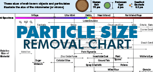
Chart displaying the sizes of well-known objects and particulates, illustrated in the size of the micrometer (micron).
View the comparison chart for particle size removal of thin-film membranes used in reverse osmosis systems.

Step by step instructions on installing replacement cartridges and sanitizing filter housings. It is highly recommended that you clean and sanitize your system once a year.

View a chart comparing the specifications of all the reverse osmosis systems we sell on this site. All bladder tanks are NSF certified.

Need to replace your system’s cartridges but not sure what type is best for your system?
View our Cartridge Replacement Guide or contact us to find out what you need.

A boil-water advisory or boil-water order is a public health advisory or directive given by government or health authorities to consumers when a community’s drinking water is, or could be, contaminated by pathogens.

Learn how to make an emergency water filter for disaster situations out of some common items.
This method does work and can keep you heathly if clean potable water or a manufactured water filter system are unobtainable.

The Hydrologic Cycle (also called the Water Cycle) is the continuous movement of water in the air, on the surface of and below the Earth.
This cycle is the exchange of energy which influences climate. When water condenses, it releases energy and warms the environment.

90% of the garbage floating in the Earth’s oceans is plastic and less than 5% of all plastic is recycled.
The patch mostly consists of pelagic plastics, formed from plastic bags, plastic water bottles, bottle caps and styrofoam.

Hydraulic fracturing (sometimes referred to as fracking or hydrofracking) is a relatively new form of natural gas extraction.
The fluids used in the fracking process flow back to the surface, often entering the water table or polluting the drilling area, and sometimes improper disposal of waste water from the wells.

As our technology advances, so do new forms of pollution and contaminants that effect our environment and our health.
Read more about drinking water contaminants and their health effects.

Chlorine has long been recognized as an oxidative agent, meaning that it not only kills the germs in the water supply; it will damage any living tissue with which it comes in contact. And your skin, like the rest of your organs, is living tissue. But that’s not the only problem.

Since the discovery of its health benefits in the mid-1940’s, fluoride is often added to the public water supplies of industrialized countries in order to reduce the populations tooth decay, which is especially effective in low income communities, where good dental hygiene may be too costly.

Chromium-6 was found in the drinking water supply of the southern California town of Hinkley and brought to national attention by Erin Brockovich.
The EPA is reviewing effects of Chromium-6 after a recent report brought to light dangerous levels in a number of major US cities.

Giardia is a flagellated protozoan parasite that colonizes and reproduces in the small intestines of humans and other animals, which can cause giardiasis.
Symptoms of Giardiasis usually show after 3 to 4 days, and include gastrointestinal and constitutional problems.

Cryptosporidiosis is a disease caused by the parasite Cryptosporidium parvum.
Since a outbreak in 1993 in Wisconson, new attention has been focused on determining and reducing the risk for Cryptosporidiosis from community and municipal water supplies.
What is reverse osmosis? What is a 4-Stage system? What are the components in a system? Visit our ‘How Reverse Osmosis Works‘ guide to find the answers.
Also see out list of contaminants RO removes and comparison chart for particle sizes to learn more about reverse osmosis.

What is ultraviolet light? Do I need to filter the water before the UV process? How exactly can light kill organisms?
Visit our ‘How Ultraviolet Purification Works‘ guide to find out how it works.

The typical water softener is a mechanical appliance that’s plumbed into your home’s water supply system. All water softeners use the same operating principle: They trade the minerals for something else, in most cases sodium. The process is called ion exchange. More…
Step by step instructions on installing replacement cartridges and sanitizing filter housings. It is highly recommended that you clean and sanitize your system once a year.

Need help installing your new RO system, how to perform maintenance, or how often to change your cartridges?
View our printable Reverse Osmosis Installation Guide to learn more.

Step by step instructions on making a connection with Quick-Connect fittings. Quick-connect fittings allow you to connect and disconnect tubing without the need of tools. For larger, plumbing size fittings read our using twist lock guide.

Step by step instructions on making a connection with Twist and Lock fittings. Twist-Lock fittings allow you to connect and disconnect tubing without the need of tools.

Step by step instructions on making a connection with SharkBite Push-To-Connect fittings. SharkBite fittings allow you to connect and disconnect pipes without the need of using PVC glue or welding copper.

Need to filter water but not sure about the differences between or applications of our systems?
Use our Water Filter Systems Guide to find out which system is best for your filtration needs.
Need to replace your system’s cartridges but not sure what type is best for your system?
View our Cartridge Replacement Guide or contact us to find out what you need.
View a chart comparing the specifications of all the reverse osmosis systems we sell on this site. All bladder tanks are NSF certified.

The size of your water softener depeneds on the total grain per day that need to be removed.
This is determined by the number of people in your household, grain per gallon (GPG) hardness and the amount of Iron present in the water.

A micron is a unit of measurement for how small of particles a filter will catch. The lower the micron size, the tinier the ‘holes’ in the filter cartridge are that allows water to pass through, ranging from 0.1 absolute to 150 microns.
Use our Pore Size Efficiency Guide to find out what micron size to use.

Pleated sediment cartridges remove dirt, rust and sediment from water while providing an increased surface area and longer life. Pleated filters down to 5 microns are washable and reusable.
Use our Pleated Sediment Cartridge Comparison to find the filter cartridge you need.

Aquariums need three types of filtration to maintain a healthy environment for freshwater, saltwater or amphibian aquariums (sediment filtration, carbon filtration, and removal of biological contaminants).

When traveling around the state or the country in a RV you might not always know where you will be getting the water from or what might be in it. Water that is stored in a RV holding tank will not stay potable for long and can become a breeding ground for algae and bacteria.

Chemicals added to public water supplies, like chlorine, can be harmful to the living cells of plants.

When brewing beer with tap or bottled water, chlorine and chloramine present in the water can combine with malt phenols in the wort to create a compound called chlorophenol, which can give the beer a medicinal taste.
View our Filtered Water for Home Beer Brewing guide.

Bottled water requires a lot of resources to manufacture and ship, and costs a lot more than reverse osmosis water.
Use our Bottled Water Cost Calculator to find out how much of an impact you have on the environment.